The fundamentals of the circuit and the interconnections of various components are illustrated in a 3-wire alternator wiring diagram. The wiring process for starters and alternators in automobiles is divided into two stages. The first stage primarily focuses on power circuit connections due to the high electrical consumption of starters and the electricity generation of alternators.
The second stage involves the control circuits. Starters and alternators are both governed by their respective control circuitry, which controls their activation, deactivation, and output regulation. Breaking down the wiring procedure makes the task easier to comprehend and leads to more predictable outcomes. Thus, it’s handy to have a 3-wire alternator wiring diagram.
When it comes to modernizing the electrical systems in their automobiles, we have a lot of options. In this guide, we’ll be comparing some of these other alternator types. For instance, the 1-wire, 2-wire, and 4-wire alternators. We’ll also look into how an alternator works, as well as how to wire, install, or even diagnose a bad alternator.
- What’s A 3-Wire Alternator Wiring Diagram?
- What Is An Alternator (And How Does It Work)
- Function Of Your Car’s Alternator
- Parts Of An Alternator
- Wire Alternator Wiring Diagram
- 1-Wire vs 2-Wire vs 3-Wire vs 4-Wire
- How To Wire An Alternator
- How To Install An Alternator
- 3-Wire Alternator – Pros & Cons
- How To Diagnose A Faulty Alternator
- Frequently Asked Questions (FAQs)
- Final Verdict
3 Wire Alternator Wiring Diagram
The 3 wire alternator wiring diagram has three electrical connections, as its name suggests. The large connector that connects to the battery is the first. The primary current flow charges the battery and drives the car when the engine is running. There are two smaller terminals on the top of the alternator, typically spade terminals.
The sense terminal is one of them. You must connect the alternator’s output to this terminal for it to sense and adjust the output voltage. The exciter is the opposite terminal. This is what energizes the alternator’s field. An alternator is a device that converts mechanical energy into electrical energy, and it’s especially useful in cars.
What Is An Alternator
The alternator is the most critical component of a car’s engine and requires no maintenance. It creates electricity, serves as a power source for automobiles, and recharges the battery. The alternator converts mechanical energy to electrical energy by switching from alternating to direct current.
The major function of an alternator is to give electricity to electrical components such as lights, fans, and windshield wipers in conjunction with the battery. It converts alternating electricity to direct current and adjusts voltage to ensure that each unit receives the appropriate minimum power.
A cooling fan, rotor, slip ring end bearings, voltage regulator, stator, slip rings, carbon brushes, diode bridge rectifier, and pulley are all included in the alternator. The fundamental units for energy generation are the rotor and stator, while the rectifier aids in converting AC to DC.
All of the components work together to monitor and manage power so that different components of the car’s engine can get the energy they require. To ensure smooth functionality of all the diverse electrical components in modern vehicles, the use of a three-wire alternator wiring diagram is necessary.
An internal regulator in alternators monitors the number of volts going to the battery. Should the voltage suddenly rise or fall, the regulator will adjust the alternator’s output to maintain a constant flow of electricity to the battery. External regulators are used in single-wire alternators, which means the regulator may be replaced if it breaks.
What Does The Alternator Do
An alternator operates in a straightforward manner. It connects to a pulley through a serpentine belt. When the engine starts, the pulley moves and rotates the rotor shafts attached to the alternator.
The rotor, which is an electromagnet, has two spinning metal slip rings and carbon brushes on its shaft. Rotation of the rotor generates a small amount of electricity, which is then transmitted to the stator.
The rotor’s magnets are strategically positioned to pass through the copper wire loops of the stator. This interaction generates a magnetic field around the coils. As the rotor rotates, it changes the magnetic field, resulting in the generation of electricity.
However, since the generated electricity is in the form of AC, it needs to be converted to DC before it can be utilized. Therefore, it passes through the diode rectifier of the alternator. The rectifier converts the alternating current into a one-way direct current. Subsequently, the voltage is directed to the voltage regulator, which adjusts it to meet the requirements of various car components.
Parts Of An Alternator
An alternator is a crucial component of a car’s electrical system, responsible for generating electrical power and charging the battery while the engine is running. To fully comprehend how an alternator works, it’s essential to understand its various parts and their functions.
In this section, we will delve into each individual component of a car’s alternator, exploring their roles and contributions to the overall functionality of this critical device.
3-Wire Alternator Wiring Diagram, Parts #1: Rotor
The rotor serves as the core of the alternator, consisting of a shaft and an electromagnet known as field windings. When the engine is running, a drive belt pulley system spins the rotor, generating a rotating magnetic field within the alternator.
3-Wire Alternator Wiring Diagram, Parts #2: Stator
The stator is a stationary part of the alternator that surrounds the rotor without making physical contact. It consists of several coil windings evenly spaced around an iron shaft. As the rotor spins, the changing magnetic field induces a voltage across the stator windings, generating alternating current (AC).
3-Wire Alternator Wiring Diagram, Parts #3: Rectifier
To convert the alternating current produced by the stator into direct current (DC), the rectifier comes into play. Typically composed of multiple diodes, the rectifier allows current flow in only one direction. By rectifying the AC voltage, the rectifier ensures a steady and consistent flow of DC power.
3-Wire Alternator Wiring Diagram, Parts #4: Voltage Regulator
The voltage regulator is a critical component that monitors and controls the electrical output of the alternator. It regulates the voltage and current supplied by the alternator to prevent overcharging of the battery and ensure a stable power supply to the vehicle’s electrical system.
3-Wire Alternator Wiring Diagram, Parts #5: Brushes and Slip Rings
The brushes and slip rings facilitate the transmission of electrical current to the rotor field windings. The slip rings are conductive rings mounted on the rotor shaft, while the brushes are carbon-based contact points that make physical contact with the slip rings.
These components enable the flow of current to energize the rotor and create the magnetic field required for power generation.
3-Wire Alternator Wiring Diagram, Parts #6: Drive Belt and Pulley
Connected to the rotor shaft, the drive belt transfers mechanical energy from the engine to the alternator. As the engine rotates the drive belt, it spins the pulley on the rotor shaft, setting the alternator in motion.
3-Wire Alternator Wiring Diagram, Parts #7: Bearings
The alternator contains several bearings to support the rotation of the rotor shaft. These bearings, including the slip ring end bearing and the drive end bearing, minimize friction and ensure smooth operation of the alternator.
3-Wire Alternator Wiring Diagram, Parts #8: Housing
The housing of the alternator encloses and protects its internal components. It is commonly made of lightweight aluminum to dissipate heat effectively, as the alternator generates significant amounts of heat during operation.
Understanding these individual components provides insight into how an alternator generates electrical power. As the rotor spins inside the stator, the magnetic field induces voltage in the stator windings. The rectifier then converts the alternating current into direct current, while the voltage regulator controls the output to maintain a stable charging voltage.
The brushes and slip rings enable the flow of current to the rotor, and the drive belt and pulley transfer mechanical energy to set the alternator in motion. All these parts work together seamlessly to ensure efficient power generation and battery charging in a vehicle.
It’s important to note that while the components discussed here are fundamental to most alternators, there can be variations in design and additional features depending on the specific make and model of the alternator.
Connections In A Wire Alternator Wiring Diagram
An alternator has a complicated wiring system because it is connected to many components. The exciter wire, as well as positive and negative wires, are the principal wirings. Exciter wire is used to turn on the voltage regulator and is linked to the L terminal of an alternator. An exciter wire is necessary to create the voltage required to start the alternator.
The positive and negative cables are small and connect to the battery’s positive and negative terminals. The alternator is also connected by the battery charging cable. It solely charges the battery and doesn’t provide power to any other devices.
The ignition input wire leading from the alternator to the key switch is likewise connected to the alternator. The ignition wire activates the voltage regulator.
Alternator Wiring Diagram
Here are several wire alternator wiring diagrams that can be utilized for a variety of applications. Let’s have a peek at their connections.
3 Wire Alternator Wiring Diagram
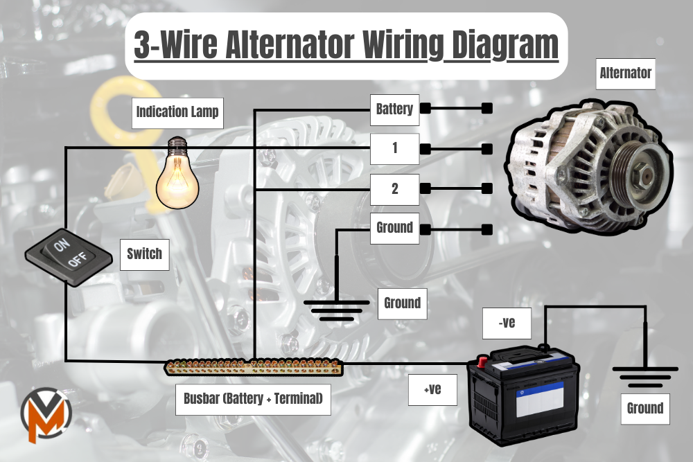
A three-wire alternator wiring diagram shows how the various components of a circuit are connected. The circuit is made up of three major wires: a positive cable for the battery, a voltage-detecting wire, and an ignition wire.
The engine is connected to the ignition input wire. The voltage-detecting cable detects the voltage and connects to the rectifier, while the power wire delivers power from the engine to the alternator.
Multi-purpose alternators with built-in voltage rectifiers for power sensing are available. Unlike single-wire alternators, they may generate and rectify electricity in the same circuit. The use of a three-wire alternator wiring diagram guarantees that all components receive controlled voltage.
Electromechanical Voltage Regulator (External)
The voltage sensor cable is coiled into an electromagnet by electromechanical regulators. This creates a magnetic field around the magnet, which attracts the iron block. Cutout relays, regulators, and current regulators are all electromagnetic switches in such circuits.
The cutout relay connects the battery to the alternator, while the regulator and current regulator switch govern the voltage output of the alternator’s field circuit. Electromechanical circuits are necessary for AC stabilizing circuits; however, they are not employed in automobiles due to their inadequate relaying mechanism.
Diagram Of PCM-Controlled Wiring
Powertrain control module voltage regulation circuits are a form of alternator that uses internal modules to control the field circuit. The PCM regulates current flow by analyzing the body control module (BCM) data and determining a system’s charging requirements.
When the voltage falls below a certain threshold, the modules are activated, causing the current flow through the coil to modify its on-time. As a consequence, the system output is modified to accommodate the system’s requirements. The PCR-controlled alternators generate the appropriate voltages in a simple but effective manner.
Why Is It Necessary To Use A 3 Wire Alternator Wiring Diagram
What’s crucial to note about the 3 wire alternator wiring diagram is that it can improve the electrical performance of your vehicle to meet your needs. A 3 wire alternator wiring diagram has three wires: the primary charge wire, a third wire that can jump between the regulator and the battery stud, and the exciter wire.
The 3 wire alternator wiring diagram is considerably less intrusive than it seems, as only two additional wires are integrated into the rest of the electrical system. Unless you are willing to rigorously manage your electrical budget when cruising at low RPM, the 3 wire alternator wiring diagram is recommended for improving your vehicle.
Wire Alternator Wiring Diagram And Function In A Car
The basic function of an alternator is to convert mechanical energy into electrical energy in an alternating manner. It is termed an alternator because it generates alternating current. The alternator function and wire alternator wiring diagram of an automobile are described in this article. We all know that an alternator is used to charge a car or an automobile. So, let’s get started.
The Function Of The Alternator In A Car
In an automobile, the alternator generates electrical energy to charge the battery. Initially, a car’s engine is started by a DC motor that draws power from the battery. As a result, there is a need to charge the battery.
The alternator is connected to the engine by a belt in an automobile. As a result, as the engine turns, the alternator rotates as well, producing alternating electrical energy. The automobile alternator contains some circuitry.
Wire Alternator Wiring Diagram
The three-wire alternator wiring diagram is used in the car, as you know now. The stator and rotor are two elements of a three-wire alternator wiring diagram. The three-phase armature winding is found in the stator, while the field winding is found in the rotor.
We understand that batteries can only store DC power. Therefore, the alternator includes a rectifier circuit that converts three-phase AC power to DC power. The field winding is connected to a voltage regulator circuit through the slip ring. The voltage regulator circuit receives the DC power from the output of the rectifier circuit and distributes it to the field winding.
The primary function of the voltage regulator circuit is to regulate the power supplied to the field winding. If the output voltage and current exceed their normal levels, the voltage regulator will decrease the power supplied to the field winding, thus reducing the voltage in the armature winding and maintaining it at a normal value.
1-Wire vs 2-Wire vs 3-Wire vs 4-Wire Alternator
For added context, here’s a brief summary of the other alternator types that you might encounter, including the 1-wire, 2-wire, and 4-wire alternators. Plus, we’ll also compare them against the aforementioned 3-wire alternator, and how they compare.
1-Wire Alternator Wiring Diagram
A 1-wire alternator, as the name suggests, uses a single wire for its operation. This setup may be less complicated, but it has its share of pros and cons.
With the 1-wire alternator, the charging circuit is simplified because the voltage regulator is internal to the alternator, and it doesn’t require external wiring. The alternator initiates its charging cycle once the engine reaches a certain RPM, which is both a pro and a con.
The advantage of a 1-wire alternator is its simplicity. It is easier to install due to fewer connections and is ideal for classic or modified cars where minimal wiring is desirable. It’s particularly useful when retrofitting an old car that didn’t originally come with an alternator.
However, the 1-wire alternator comes with some drawbacks. Its self-exciting nature means the charging process does not commence until a certain engine RPM is attained. This is often not an issue for highway driving but can lead to charging problems at lower RPMs or idle speed, leading to possible battery drainage.
1-Wire vs 3-Wire Alternator
Comparing the 1-wire and 3-wire alternators, the 3-wire alternator has an advantage in that it continuously monitors the electrical needs of the vehicle through a sensing wire to the battery. It adjusts the charge output accordingly, ensuring optimal charging regardless of the engine’s RPM.
On the other hand, a 1-wire alternator doesn’t have a sensing wire, so it can’t detect voltage dips beyond the battery. This limitation means that while a 1-wire alternator is simpler to install, it might not offer the same level of performance and reliability as a 3-wire alternator, particularly at low RPMs.
2-Wire Alternator Wiring Diagram
A 2-wire alternator is a step above the 1-wire model. In this system, one wire is the output to the battery, and the other is the ignition input or ‘exciter’ wire. The exciter wire is used to provide a small amount of electricity to start the alternator charging.
Like the 3-wire setup, the 2-wire alternator senses voltage through its ignition input wire, allowing it to adjust the charge output to match the vehicle’s electrical needs more accurately than a 1-wire alternator.
The 2-wire system offers more reliable charging than the 1-wire setup, especially at low engine speeds, and is less complex than the 3-wire setup. However, it may not be as accurate as the 3-wire system in monitoring and adjusting the charge output.
2-Wire vs 3-Wire Alternator
In comparison to a 3-wire alternator, a 2-wire alternator lacks a sense wire directly connected to the battery. This means it cannot as accurately determine the overall electrical system voltage. Therefore, while it’s more reliable than the 1-wire system, it may not fully match the performance and reliability of a 3-wire alternator.
4-Wire Alternator Wiring Diagram
A 4-wire alternator takes the functionality of the 3-wire system a notch higher. It consists of the battery output wire, the ignition input or exciter wire, the sensing wire, and a fourth wire connected to the voltage regulator.
This additional wire to the voltage regulator allows more precise control of the alternator’s output, ensuring optimal charging at all engine speeds and better performance than the other types. This is particularly useful in modern vehicles with more extensive electrical systems and demand.
The 4-wire alternator setup, however, requires more wiring and may be more complicated to install and troubleshoot. But for modern vehicles with significant electrical loads, the benefits are worth it.
4-Wire vs 3-Wire Alternator
The advantage of a 4-wire alternator over a 3-wire system is the additional wire connected to the voltage regulator, providing a more precise response to voltage changes. However, its more complex setup may pose challenges during installation and maintenance.
For cars with less electrical demand, a 3-wire alternator might be a better fit, striking a balance between performance and simplicity.
How To Wire An Alternator
You will know how simple it is to connect a new 3-wire alternator to update your old vehicle in the steps below. You’ll be done in no time if you stick to them.
1. Unplug the Negative Terminal of the Vehicle Battery
Remove the negative terminal from the vehicle battery before starting anything. This is not a difficult chore to complete. However, anything involving electricity or the vehicle battery should be approached with caution.
2. Assemble the Alternator Mounting Brackets
The second phase of your new endeavor could be the most difficult. But don’t worry, anything is achievable if you know how to do it correctly. It’s also worth noting that you might be able to find brackets in a junkyard that will work with minimal changes, which will save you money.
Another advantage is that you can make your own brackets out of 14-inch flat stock steel that is about 1 inch wide if you can’t find them in a junkyard. This is yet another wonderful approach to saving money while still improving your old vehicle.
The brackets would then be mounted using the generator bracket’s original mounting holes in the engine block. It is critical to ensure that the pulleys are properly aligned with the belt and that the bracket allows for drive belt adjustment. After that, the alternator and new drive belt can be attached.
3. Connect the Positive Terminal Of The Battery To The Output Bolt
You’re halfway done, and you’ve already completed the most difficult portion. Connecting the output bolt on the back of the alternator to the positive terminal of the battery with 10-gauge wire and solderless ring terminals is the next step in enhancing your ancient automobile.
This connection can also be made on the starter solenoid, which is where the positive cable is connected. Then, connect the battery’s positive terminal to the starter solenoid.
4. Plug-In the Negative Battery Cable
Connecting the battery negative cable is the final step in upgrading your antique vehicle with a 3 wire alternator wiring diagram. You may improve the performance of your antique vehicle while also saving money by installing a 3-wire alternator.
The AC Delco 3 wire alternator wiring diagram is used in most GM products as well as various types of heavy equipment. This 3 wire alternator wiring diagram is remarkable in that it has a high output, a compact construction, and is simple to operate.
The required brackets can be used to convert this alternator to any vehicle or engine-powered equipment in just a few simple steps. To wire this alternator, you won’t need any special skills; anyone with average mechanical abilities should be able to do it.
5. Unplug the Battery’s Negative Terminal
The first step in wiring a 3 wire alternator wiring diagram to your vintage vehicle is to disconnect the battery negative terminal, as I explained in the preceding step-by-step guide. This is a crucial step that should not be skipped.
6. Connect The Wire To The Output Stud
The next step is to use a solderless ring connector to connect a piece of 10-gauge wire to the output stud on the rear of the alternator. The starter solenoid should be linked to the other end of this wire. Connecting it to the same terminal as the positive battery line requires simply a few simple steps.
7. Connect The Alternator Connector To The Receptacle Of The Alternator
The next step is to connect the new alternator connector to the receptacle on the alternator. It’s not difficult to solder a 14-gauge wire to the smaller pigtail from the connector. This wire connects to the IGN terminal on the ignition switch. Finally, connect a small 12-volt caution light in series with this cable in this step.
8. Splice A 10-Gauge Wire To The Bigger Wire On The Alternator Plug
Splicing a 10-gauge wire to the bigger wire on the alternator plug is one of the final stages in connecting an AC Delco 3-wire alternator to your vehicle. Connect the wires with a solderless connector to complete the procedure.
Make sure the wire is long enough to connect to the same starter solenoid terminal as the positive battery cable and the alternator output wire. Finally, use a solderless ring connection to attach the wire to the terminal. After this step, you’re practically done.
9. Putting The Final Touches On It
Connecting the battery negative terminal to the AC Delco 3 wire alternator wiring diagram is the final step in wiring it to your vehicle. After you’ve finished wiring, you’ll be able to utilize it and operate it with ease.
Your vehicle will run more efficiently and be improved to a whole new level if you replace the old generator with a 3 wire alternator wiring diagram. Your enhanced vehicle will allow you to work more efficiently, which is every owner’s ultimate desire.
How To Install An Alternator
Once you’ve understood what the 3-wire alternator wiring diagram meant, you could even figure out how to install an alternator into your car…
3-Wire Alternator Installation, Step #1: Gathering Essential Tools
To ensure a successful alternator replacement, you’ll need specific tools on hand. These include a set of wrenches, a screwdriver set, and a battery terminal cleaner. Optional but helpful tools include a wire crimping tool and a soldering iron. Ensuring your tools are in good working condition before beginning is vital.
3-Wire Alternator Installation, Step #2: Battery Disconnection
Before proceeding with the alternator replacement, disconnect your vehicle’s negative battery terminal. This preventive measure protects you from electrical shocks or other related hazards during the installation process.
3-Wire Alternator Installation, Step #3: Removal of the Old Alternator
Once you’ve secured your safety, use your wrench set to remove the necessary bolts and hardware from your old alternator. Upon removal, ensure you dispose of the old alternator responsibly.
3-Wire Alternator Installation, Step #4: Installing the New 3-Wire Alternator
Now comes the central part of the process: installing your new 3-wire alternator. Carefully position it and secure it using the provided bolts or other necessary hardware. Make certain all connections are tight and secure for the optimal performance of your new alternator.
3-Wire Alternator Installation, Step #5: Wiring the New Alternator
Next, focus on connecting the new alternator’s wiring. The black wire from the alternator connects to the negative terminal on your vehicle battery, the red wire to the positive terminal, and the white wire to a grounding point. If you’re unsure about these connections, refer to your vehicle’s manual for clarification.
3-Wire Alternator Installation, Step #6: Testing the Installation
After connecting all the wiring, turn on your vehicle’s ignition to test the new alternator. If all connections are working as they should, the new alternator will start up and supply power to your vehicle. After a successful test, turn off the ignition and complete the installation of any remaining hardware.
Pros & Cons Of A 3-Wire Alternator
But, before you consider installing a 3-wire alternator into your car, bear in mind its respective pros and cons…
Pros of a 3-Wire Alternator
Durability: 3-wire alternators boast a design that allows for separate current regulation, reducing strain on the system and enhancing its efficiency. This makes these alternators less likely to fail over time, compared to their two-wire counterparts.
Cost-Effectiveness: Despite a slightly higher upfront cost, a 3-wire alternator requires less maintenance and fewer repairs over time. This means more savings in the long run.
Improved Performance: The 3-wire system boosts the alternator’s efficiency and power output, providing more stability and better electrical output. This is crucial for vehicles with complex electrical systems, like high-performance cars or motorcycles.
Enhanced Safety: The separate current regulation of a 3-wire alternator helps prevent system overloads and short circuits, making it a safer option for all types of vehicles.
Cons of a 3-Wire Alternator
Despite the numerous benefits of 3-wire alternators, there are potential downsides to consider. These include a higher initial cost compared to two-wire models and potential complexity in wiring, particularly for those less familiar with automotive electrical systems.
However, the long-term savings, enhanced performance, and increased safety often outweigh these potential cons. With the right information and preparation, installing a 3-wire alternator can be a highly beneficial move for your vehicle.
Diagnosing A Bad Alternator
Besides looking into how to wire a 3-wire alternator based on a wiring diagram, here’s a quick guide on how you can diagnose a faulty alternator:
Before we dive into hands-on diagnosis, let’s discuss some early indicators of a problematic alternator. Some of the most common signs are dashboard warning lights, dimmed headlights, slow power accessories, a weak battery, or a burning rubber smell. If your car exhibits any of these symptoms, the alternator may be the culprit.
Step 1: Inspection of Battery and Alternator Connections
Your initial step in diagnosing a faulty alternator should involve examining the battery and alternator connections. Confirm all cable connectors are secure, clean, and devoid of corrosion. If you discover corroded or worn parts, prioritize replacing them before proceeding.
Step 2: Voltage Test for Alternator Output
After securing all connections, testing the alternator’s output is the next step. To do this, connect a reliable voltage meter to the battery terminals. An output reading of less than 13 volts could signal the alternator’s struggle to generate sufficient power.
Step 3: Comprehensive Wiring Review
If your alternator’s output falls below the 13-volt threshold, examine your wiring. Every wire should be securely connected and free from corrosion. Promptly replace any corroded or damaged wires with new ones to avoid future complications.
Step 4: Checking the Voltage Regulator
The voltage regulator is a significant part of the alternator and may be the root cause of many alternator problems. Using a multimeter, check the voltage regulator’s output. If the output is erratic or out of the acceptable range, your regulator might need a replacement.
Step 5: Inspecting the Alternator Belt
A slipping or damaged alternator belt can cause low output. Inspect the belt for wear, tightness, and proper alignment. If it’s loose, tighten it. If it’s damaged or worn, it might be time for a replacement.
Step 6: Assessing the Diode Rectifier
A defective diode rectifier may reduce the alternator’s output. While this component is a bit more challenging to test, an auto parts store can often do it for you. If the rectifier is faulty, you may need a new alternator, as many modern cars have these parts integrated.
Step 7: Double-checking Connections
Loose connections can cause occasional electrical issues, which can be frustrating to pinpoint. Ensure all connectors are securely connected and free of corrosion. Tighten any loose connections, or replace them as necessary.
Step 8: Consider Replacing the Alternator
If you’ve carried out all the steps and the issue persists, it may be time to replace your alternator. Ensure the replacement matches the model and output capacity of your current alternator. After securing the new part, follow the correct installation instructions for a 3-wire alternator.
By adhering to these guidelines, you should be able to diagnose most issues with your 3-wire alternator. Remember, safety always comes first when dealing with electrical systems. Always wear protective eyewear and gloves, and if you’re unsure about anything, consider consulting with a professional mechanic.
FAQs – 3-Wire Alternator Wiring Diagram
Here are some interesting and popular FAQs around the 3-wire alternator wiring diagram…
What’s The Difference Between A One-Wire Alternator And A Three-Wire Alternator?
The 1-wire alternator only knows what it’s providing current to; the battery. The three-wire alternator detects the voltage at the fuse block and ignition, and the alternator will charge more to bring all of the systems up to power.
On An Alternator, What Are The Two Little Wires?
The positive and negative cables are the two wires that connect to the alternators. The alternator (S) terminal is connected to the (B+) circuit with a jumper wire.
What Does An Alternator’s Exciter Wire Do?
An alternator is a car component that transfers power from the fuel system to the battery, allowing vehicle accessories like the radio, headlights, and air conditioning fans to operate. When a car is started, an exciter wire generates the voltage required for the alternator to begin operating.
On A Wire Alternator Wiring Diagram, What Are The Three Terminals?
The battery positive wire, the voltage sensor wire, and the ignition input wire are the three-wire types in a three-wire alternator wiring diagram. The positive wire from the battery is connected to the starter. The voltage-detecting wire is connected to the battery, while the ignition wire is connected to the key switch from the alternator.
With A Screwdriver, How Do You Inspect An Alternator?
Start your car by turning the ignition key to the “on” position. The voltage regulator is turned on, and the dashboard warning lights illuminate. Use the screwdriver to repeat the test. Place the screwdriver’s metal end towards the nut on the alternator pulley.
On An Alternator, What Do The Letters R And F Mean?
The ‘Reference’ or voltage sense terminal and the ‘Field’ terminal are the R and F terminals, respectively.
On A Wire Alternator Wiring Diagram, Which Wires Go Where?
Connect the positive cord to the positive terminal of the alternator. One cable connects to the starter motor, while the other connects to your battery if your alternator has two positive terminals. The two positive cables will be red and will be located nearby.
Where Should The Alternator Wire Be Connected?
Either the wire directly connects to the battery or it connects via a connector in the main battery supply circuit. Typically, it connects to the battery side of the fuse block. Its purpose is to monitor the system voltage and adjust the charging rate accordingly, depending on the system load or battery status.
How Do You Connect An Alternator To A Battery Directly?
The “battery charging wire” connects the main hub to the battery. In these systems, the battery charging line simply charges the battery and does not operate the electrical system. In many other autos, the alternator output line connects directly to the battery (or to the battery-positive cable at the starter solenoid).
What Is The Best Way To Tell If My Alternator Has An Internal Regulator?
The alternator is internally regulated if the pins on the side are aligned in the form of “- -“. Find a regulator under the washer bottle or a bracket on the driver’s side of the radiator support.
How Does an Alternator Work
An alternator works by using the engine’s mechanical energy to produce electrical power. This mechanical energy turns a magnetic rotor inside the alternator’s wire coil. This action generates an electric current. As the rotor turns, it creates an alternating current which the alternator then converts into direct current, the type of power your car’s electrical systems use.
Where Is the Alternator
The alternator is usually found at the front of the engine. It’s connected to the engine’s crankshaft by a belt. The crankshaft drives the belt when the engine is running, providing the rotational force needed to generate electricity in the alternator.
What Does an Alternator Look Like
An alternator resembles a small, metal canister. It has a pulley on one side that connects to the engine with a belt. The backside has several connectors for the electrical wires, including the three wires in a 3-wire alternator setup.
Is It the Battery or the Alternator
A car might have a problem starting due to issues with the battery or the alternator. If the car doesn’t start but the lights and electronics work, it’s likely the battery. If the car starts but the lights and electronics are dim or erratic, it could be the alternator failing to charge the battery.
How Does an Alternator Charge a Battery
The alternator charges the battery by supplying it with direct current electricity. When the engine is running, the alternator produces electricity which is then used to replenish the battery. It ensures the battery stays charged and is ready to start the car the next time you turn the ignition.
How to Wire an Alternator as a Generator
Wiring an alternator as a generator requires you to connect the battery to the alternator. Connect the positive terminal of the battery to the B+ terminal of the alternator. Connect the field wire to the F terminal and the sensing wire to the S terminal. Ensure the alternator’s case is grounded.
How to Wire an Alternator to Charge a Battery
To wire an alternator to charge a battery, connect the alternator’s output terminal to the battery’s positive terminal. The alternator’s ground terminal is connected to the battery’s negative terminal or the car’s chassis. Make sure the connection is secure and the wiring is correctly insulated to prevent electrical shorts.
What Is the Purpose of an Alternator
The purpose of an alternator is to generate electricity for the car’s electrical systems and to keep the battery charged. This includes powering the lights, radio, and other onboard electronics while the engine is running.
How to Excite an Alternator
Exciting an alternator means providing it with an initial charge to start the power generation process. This is done by applying a voltage to the field wire, often through the ignition switch. Once excited, the alternator will begin producing electricity.
What Are the 3 Wires for on a Alternator
The three wires on an alternator are the battery wire, the field wire, and the sensing wire. The battery wire carries the generated electricity to the battery. The field wire carries voltage to the alternator to excite it. The sensing wire monitors the battery voltage to regulate the alternator’s output.
How to Wire a One Wire Alternator
Wiring a one wire alternator is simple. The single wire connects the alternator’s output to the battery’s positive terminal. This wire carries the generated electricity to the battery for charging and to power the car’s electrical systems.
Can You Test an Alternator Without Removing It
Yes, you can test an alternator without removing it. Use a multimeter to check the voltage at the battery terminals while the car is running. A normal reading should be between 13.6 and 14.6 volts. If it’s lower, the alternator might not be working properly.
How to Bench Test an Alternator
To bench test an alternator, remove it from the vehicle and set it up on a secure surface. Connect a voltmeter to the alternator’s output terminal and ground. Apply voltage to the field wire to excite the alternator. The voltmeter should read between 13.6 and 14.6 volts if the alternator is functioning correctly.
How Much Copper Is in an Alternator
The amount of copper in an alternator can vary, but generally, an average-sized car alternator might contain around a pound of copper. The copper is found primarily in the stator and rotor windings, where it forms the conductive pathways that generate electricity.
3 Wire Alternator Wiring Diagram Essential Knowledge
- An alternator is a crucial component in a car’s engine that generates electricity, provides an electrical supply to cars, and recharges the battery.
- The alternator converts mechanical energy into electrical energy and changes alternating current to direct current.
- The main components of an alternator include a cooling fan, voltage regulator, rotor, stator, diode bridge rectifier, slip rings, slip ring end bearings, carbon brushes, and pulley.
- The rotor and stator are the central units for electricity generation, while the rectifier helps in converting AC to DC.
- Wiring an alternator can be complex as it involves connections to multiple components, including the exciter wire, positive and negative cables, the battery charging wire, and the ignition input wire.
- There are different types of alternator wiring diagrams, including the three-wire alternator wiring diagram, external electromechanical voltage regulator, and PCM-controlled wiring diagram.
- The three-wire alternator wiring diagram is a multi-purpose alternator that has built-in voltage rectifiers for power sensing, ensuring regulated voltage for all components.
- The external electromechanical voltage regulator involves coiling the voltage sensing cable into an electromagnet and attracts the ferrous block towards itself.
- The PCM-controlled wiring diagram is an advanced type of alternator that uses internal modules to control the field circuit of an alternator and is very efficient.
Final Verdict, Wire Alternator Wiring Diagram
Alternators keep an automobile running once the engine has started. Additionally, alternators require complex wiring, and they need to connect the wires to the correct units and terminals. Moreover, designing alternator wiring schematics simplifies this process. Specifically, an alternator wiring diagram illustrates how the connections and physical layout of a circuit are connected.
Furthermore, it’s easier to establish circuits and connect the alternator appropriately when you have a clear picture of each component’s wiring connections and position. In fact, it is vital to create circuits with adequate wiring to give each piece of equipment a proper voltage, ensuring that none is over or underpowered.
I cannot get alternator to charge–dum light will only light if grounded–1157 from tail light,perhaps this light is too big?New alternator 40amp made to fit l3e Mitsubitshe(diesel)Will a small LED type light work as a dummy?Please help thank you
It seems like you’re having trouble getting your alternator to charge, and you’ve mentioned that the dummy light only lights up when grounded. It’s possible that the 1157 bulb from the tail light might be too big for the dummy light function.
Using a small LED type light as a replacement for the dummy light could be worth trying. LED lights generally have lower power requirements and might be more suitable for this purpose. However, it’s important to ensure that the LED light you choose matches the specifications and requirements of your alternator and vehicle.
If you decide to go ahead with the LED light, make sure it can handle the voltage and current output of your alternator. Additionally, check if any modifications or adjustments need to be made to the wiring diagram to accommodate the use of an LED light.
It’s also worth considering other potential issues that could be causing the alternator not to charge. Double-check all connections and wiring to ensure they are secure and correctly installed. If you’re still experiencing difficulties, consulting a professional or an experienced mechanic might be beneficial in troubleshooting the problem more effectively.
I hope this helps, and good luck with resolving the issue with your alternator!
hi ,i have a bosch alternator with three screw on connections but only two wires the red feed and another thinner one,i took it off car and now cant remember where the thin one goes to, of the two smaller connections one has a positive symbol the other has nothing , where do i put small wire from somewhere around engine
Hi Charles,
In a typical Bosch alternator with three screw-on connections, here’s how they are usually configured:
1. B+ Terminal (Positive Symbol): This is the main power terminal and is typically connected to the battery or the positive side of the electrical system. It should have a thick wire (usually red) attached to it, which goes directly to the positive terminal of the battery. This terminal provides power to the alternator to charge the battery and power the vehicle’s electrical systems.
2. D+ or W Terminal: The second small terminal with no symbol (blank) or marked “D+” or “W” is typically the exciter terminal. It is used to provide the initial voltage to activate the alternator when the ignition is turned on. This terminal should be connected to the ignition switch, typically through a warning light or indicator on the dashboard. When you turn on the ignition, this terminal receives voltage, and the alternator starts generating power.
3. DF Terminal (Optional): In some Bosch alternators, there might be a third terminal labeled “DF.” This terminal is used for various purposes, such as controlling the alternator’s output voltage. It may not always be present in every alternator, and its function can vary depending on the specific alternator model.
Based on your description, it sounds like the thinner wire you have may be the exciter wire (D+ or W terminal). This wire should typically be connected to the ignition switch or a warning light in the dashboard. It’s essential to consult the wiring diagram for your specific vehicle or the alternator model to ensure the correct connection.
If you’re unsure about the wiring or don’t have access to a wiring diagram, I recommend seeking assistance from a qualified mechanic or an automotive electrical specialist who can help you properly connect the wires to avoid any electrical issues. Incorrect wiring can lead to alternator or electrical system problems in your vehicle.
i have three terminals on my alternator and only two wire which one do i leave